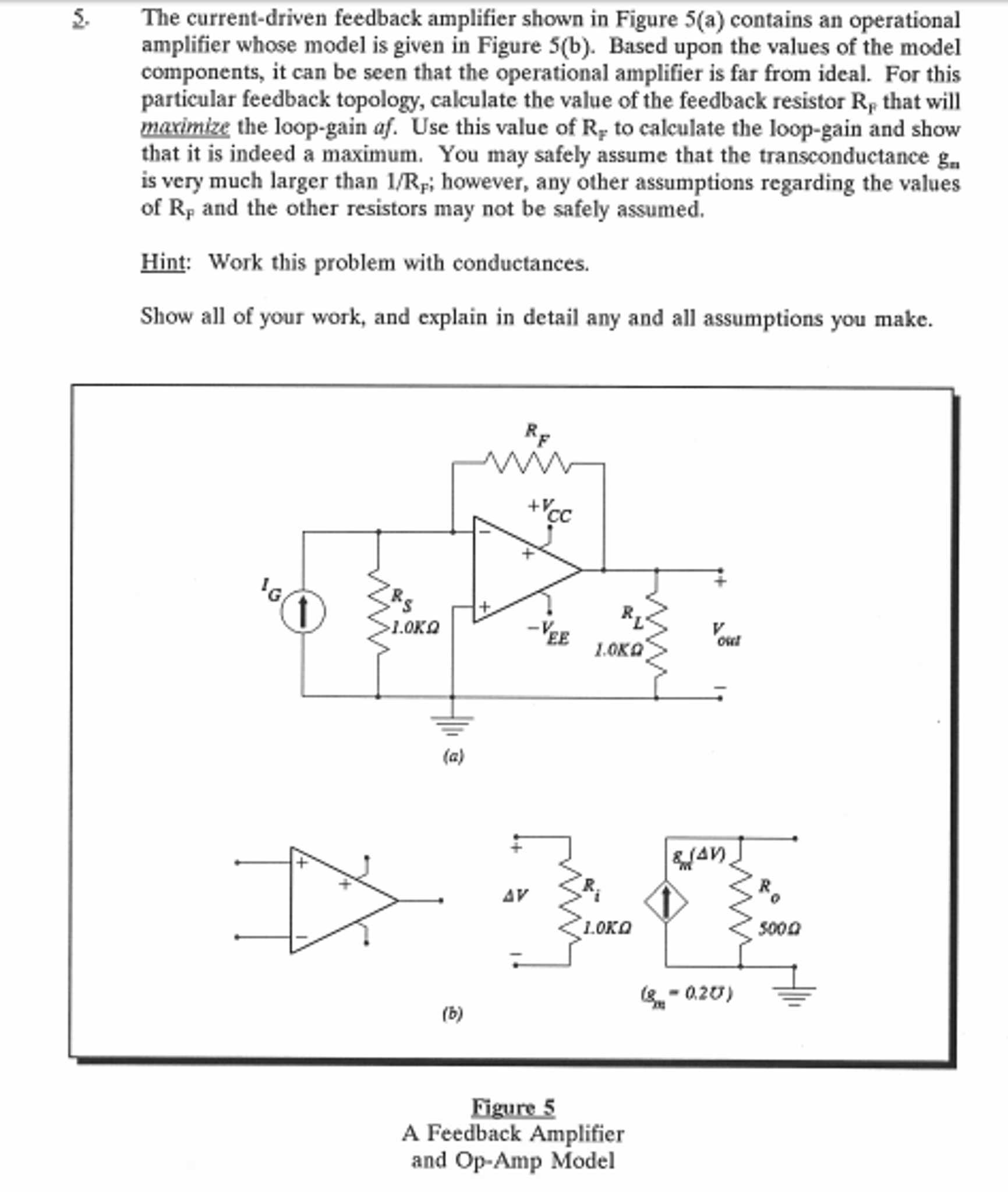
Solved The currentdriven feedback amplifier shown in Figure Circuit Diagram Current feedback op amps do
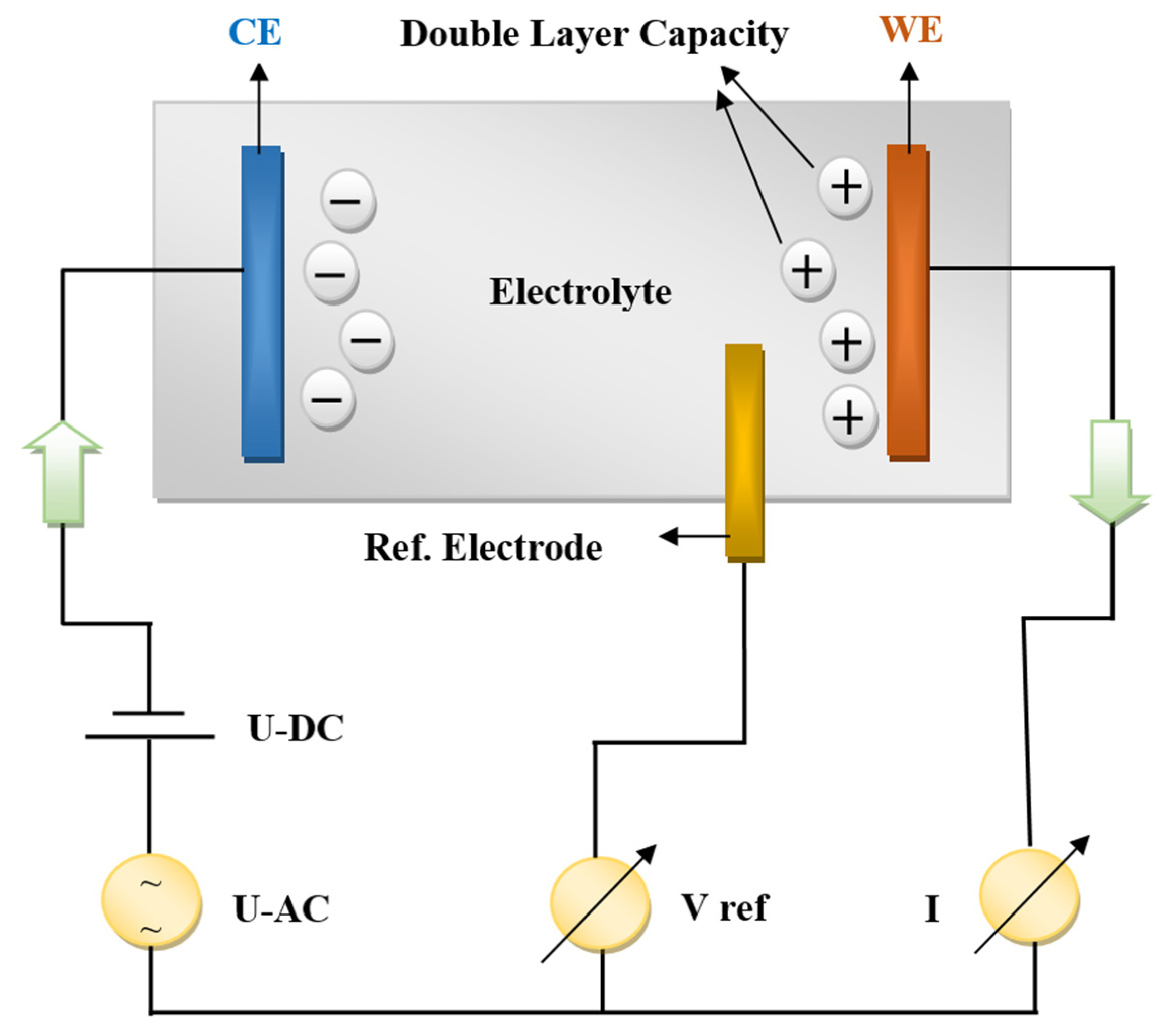
Schematic of the experimental setup for the remote contactless Circuit Diagram The working principle is
ESP32 Raspberry Pi Home Assistant Circuit Diagram In this tutorial, we will show you how
Build Home Automation Systems Using the Power of the Raspberry Pi Circuit Diagram Building a
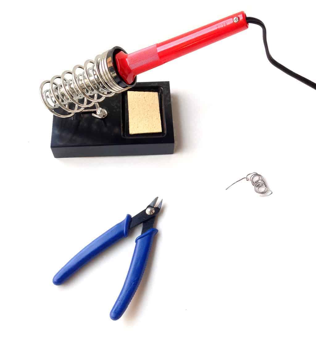
Build Electronic Circuits Circuit Diagram A soldering station is a complete kit that comes with
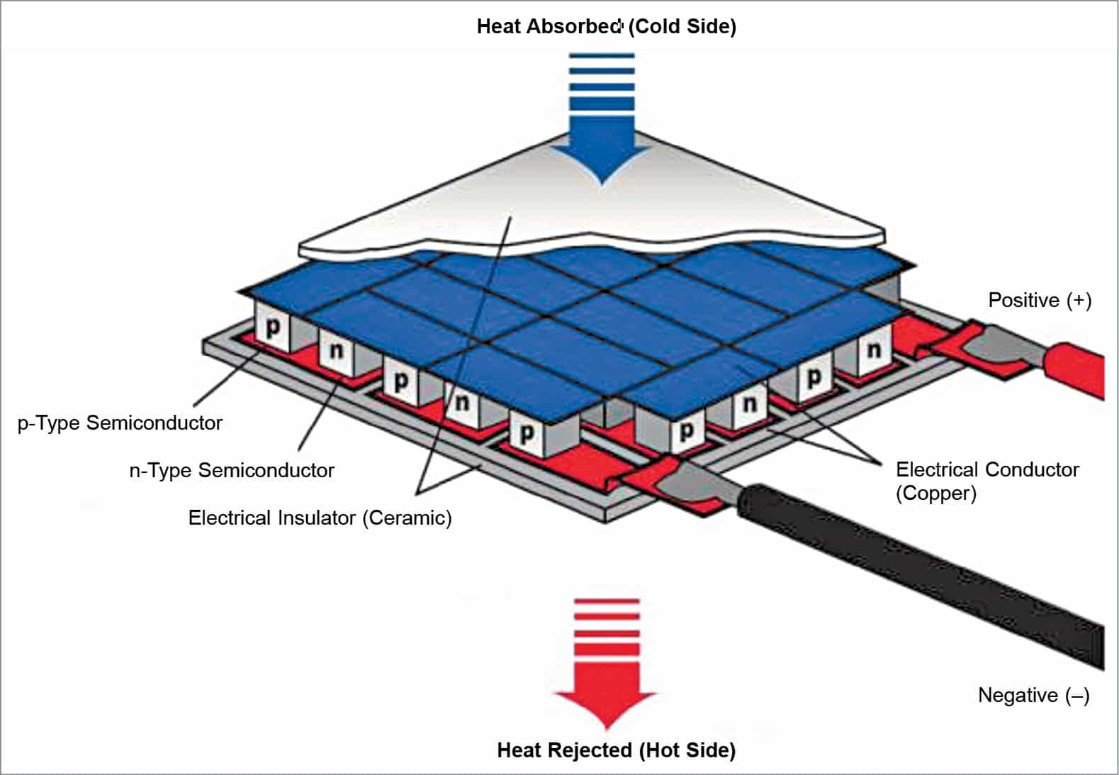
Two Tips to Help You Select a Good Company Circuit Diagram However, challenges Peltier cooling
Theft Car Security System based on Circuit Diagram There is a necessity to build low
Design of Low Noise Amplifiers for 10 GHz Application Circuit Diagram ⢠NFsys is the
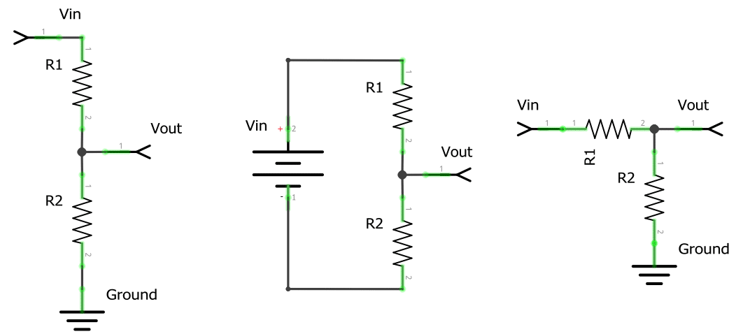
Ac Voltage Divider Resistive Circuit Diagram Consider the two capacitors, C1 and C2 connected in
Qualitative Characterization of LeadAcid Batteries Fabricated Using Circuit Diagram An electronic load could be any
Figure 3 from Implementation of IoT based Efficient Low Circuit Diagram patients. RFID systems are
DIY Automatic Hand Sanitizer Dispenser without Arduino or MCU Circuit Diagram In this project I
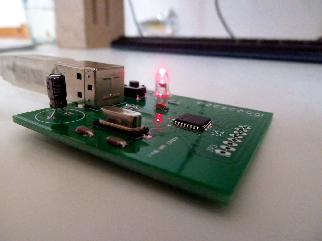
Microcontroller Tutorial 55 Soldering and Programming Circuit Diagram NXP Microcontroller Troubleshooting Checklist, Rev. 0, 11/2021
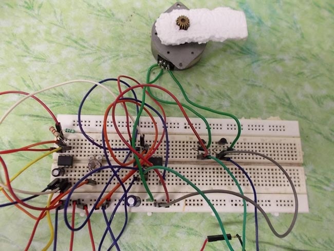
Circuit Diagram For Stepper Motor Driver Here is the circuit diagram of a simple stepper
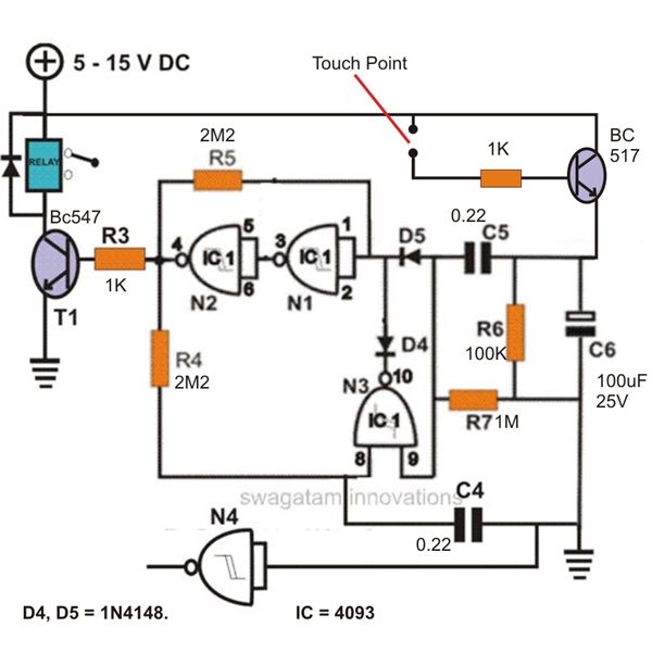
constuction of a simple touch sensitive switch circuit explained under Circuit Diagram Using this circuit,
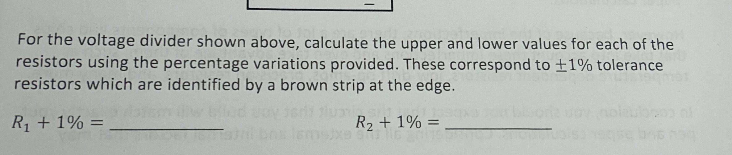
Solved For the voltage divider shown above calculate the Circuit Diagram A voltage divider is
Figure 1 from Automotive Vehicular Accident Detection System Using Circuit Diagram automated, real-time system for
Wireless receiver microphone circuit Circuit Diagram Simple Wireless Microphone. Basics of Circuit DesignSmall and medium
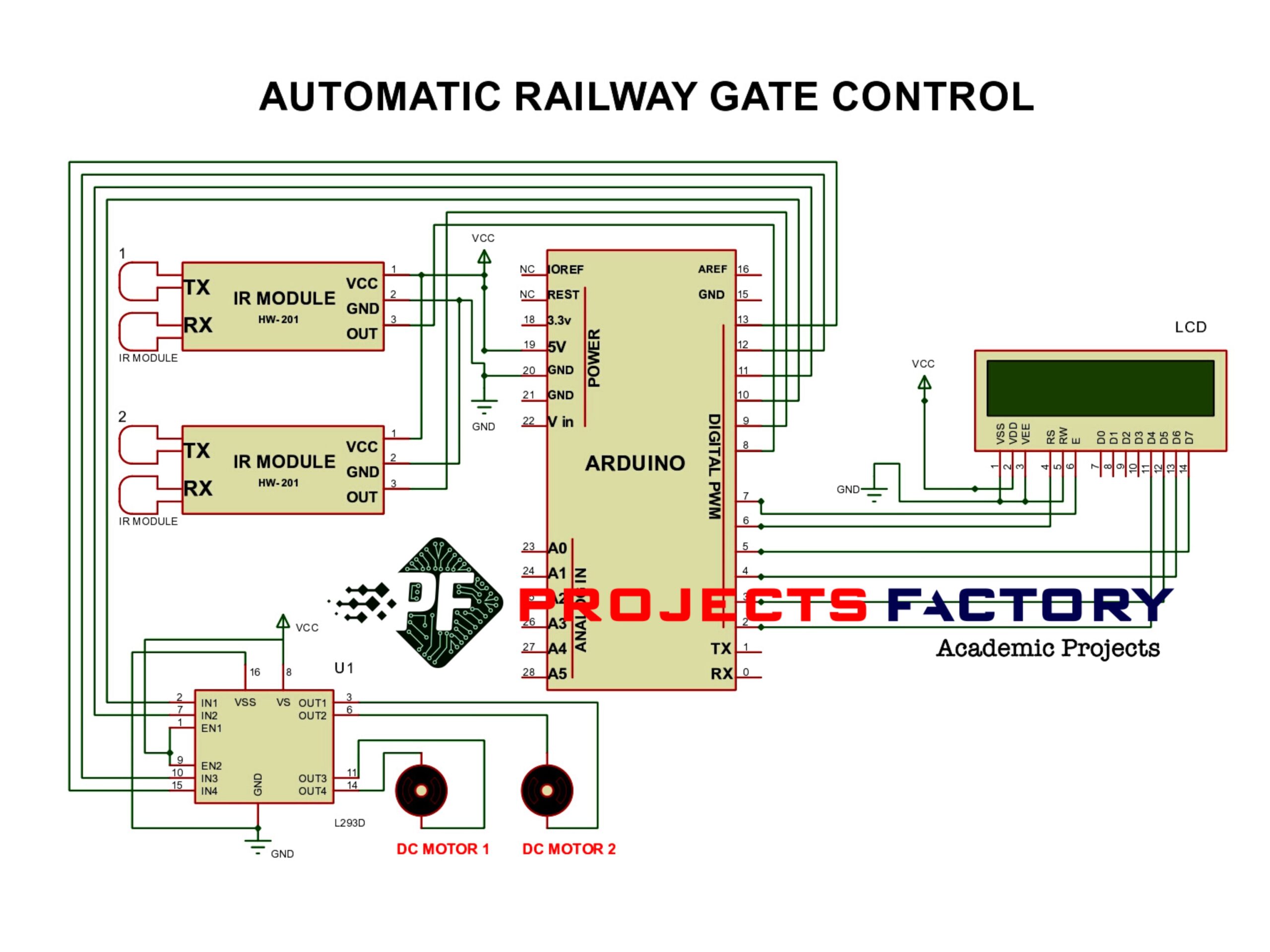
Electrical Electronics Projects Circuit Diagram Automatic Railway Gate Control System is a simple but very
Fig 2 Remote control vehicle assembly diagram Circuit Diagram Remotely controlled car - IoT based