How to Make Emergency Light Circuit Diagram Components used in Automatic Emergency Light circuits are
2 Circuit Diagram Same as the first graph, a sound sensor have four pins. VCC
The Electric Vehicle Lithium Battery Monitoring System Circuit Diagram This IC is capable of active
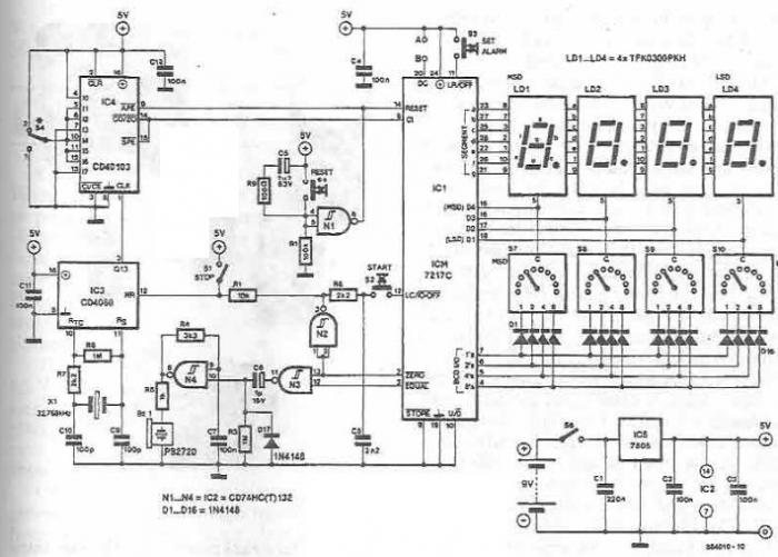
Electronic Timer with display circuit Circuit Diagram Here, a 4-step programmable timer circuit is shown,
How to Make Light Sensitive Light 3 Steps Circuit Diagram Here are just a few
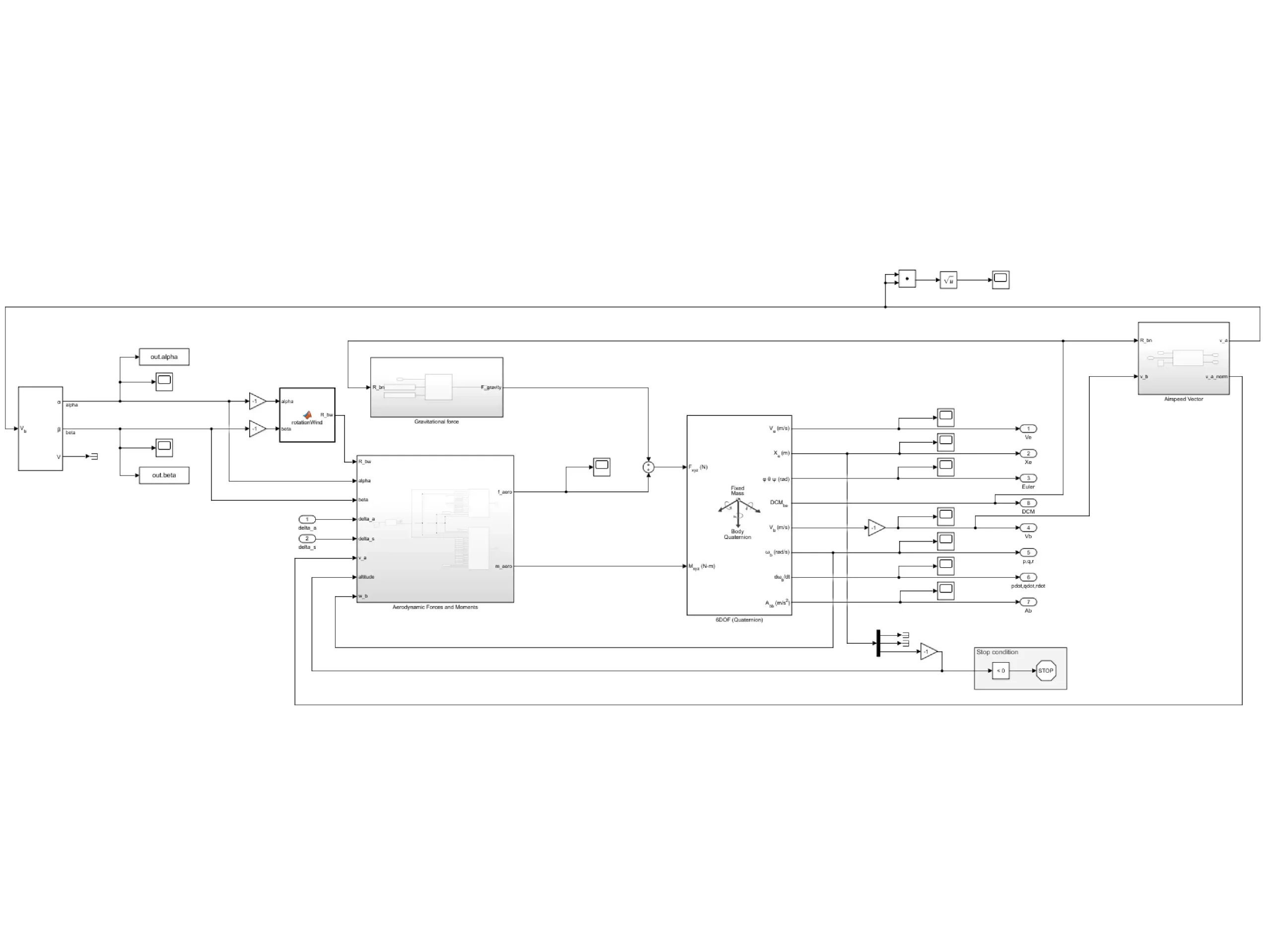
Simple Drone Circuit Diagram Once the flight controller is calibrated, the pilot can then start
DIY Arduino Powered Lie Detector Circuit Diagram Lie Detector Circuit Diagram Lie Detector Working. This
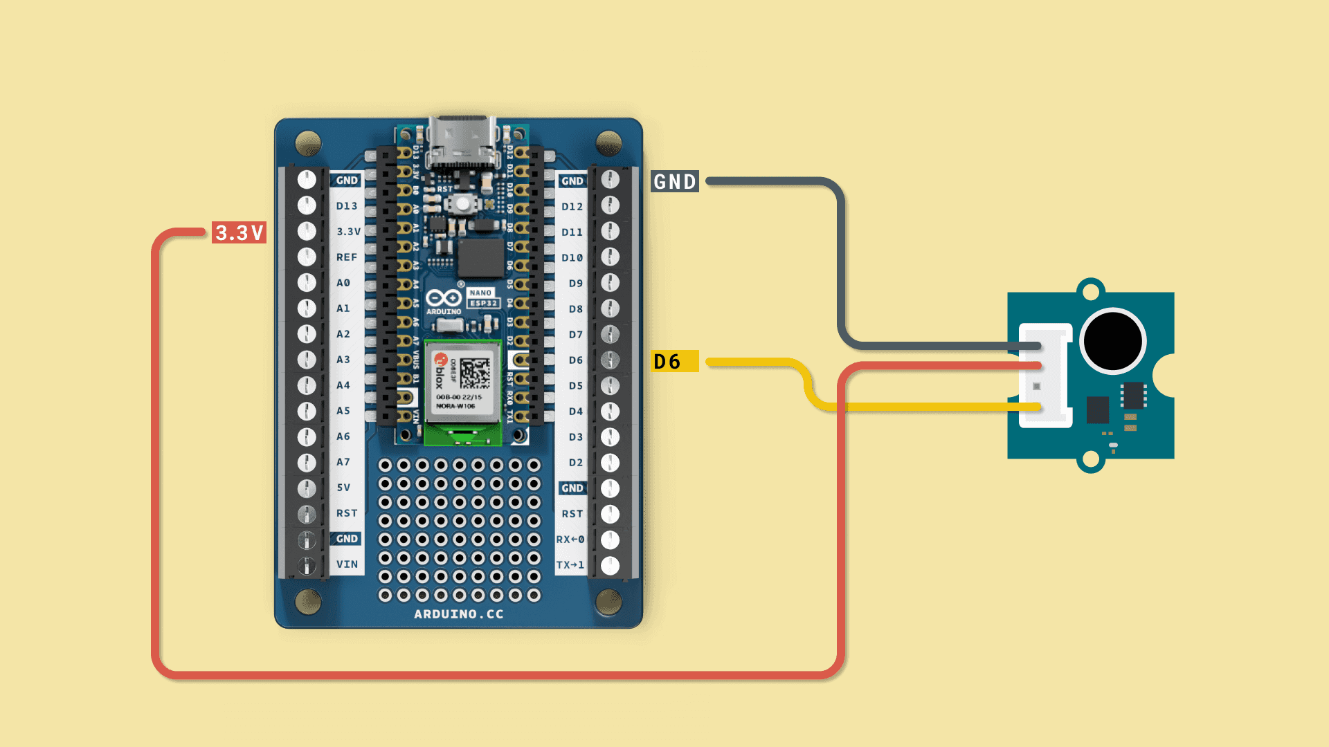
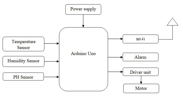
IOT based Green House Monitoring and Controlling Using Arduino Circuit Diagram Air Temperature and Humidity
SOLUTION Study material bipolar junction transistor bjt configurations Circuit Diagram If you have checked out
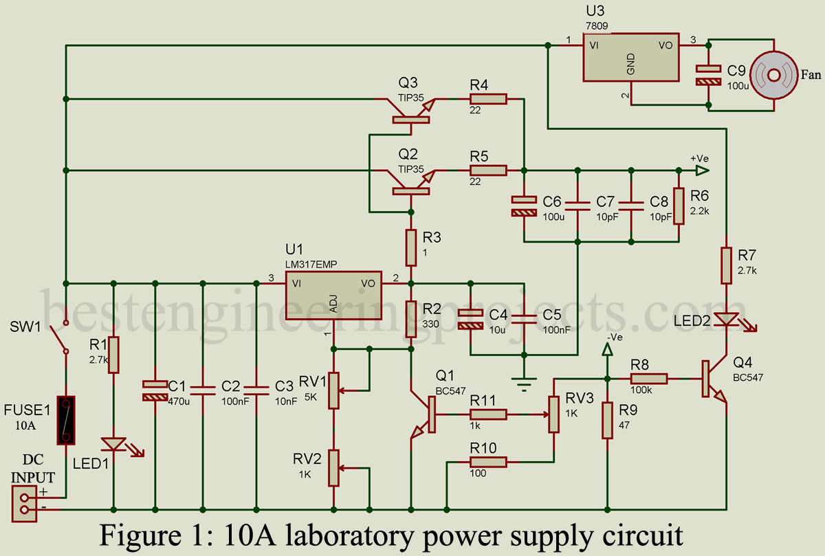
Power Supply Circuit Diagram POWER SUPPLY DESIGN BASICS by P. ANTONIAZZI In mains-supplied electronic systems
Frequency Response Analysis Circuit Diagram This then allows such circuits to be studied using frequency
Electronic board for football game score Circuit Diagram Through this circuit, we use two buttons
Voice controlled home automationpptx Circuit Diagram Control home appliances manually without internet. Monitor real-time feedbacks
Sound filtering circuit will this work Circuit Diagram Create Custom Sounds and Filter Audio. square,
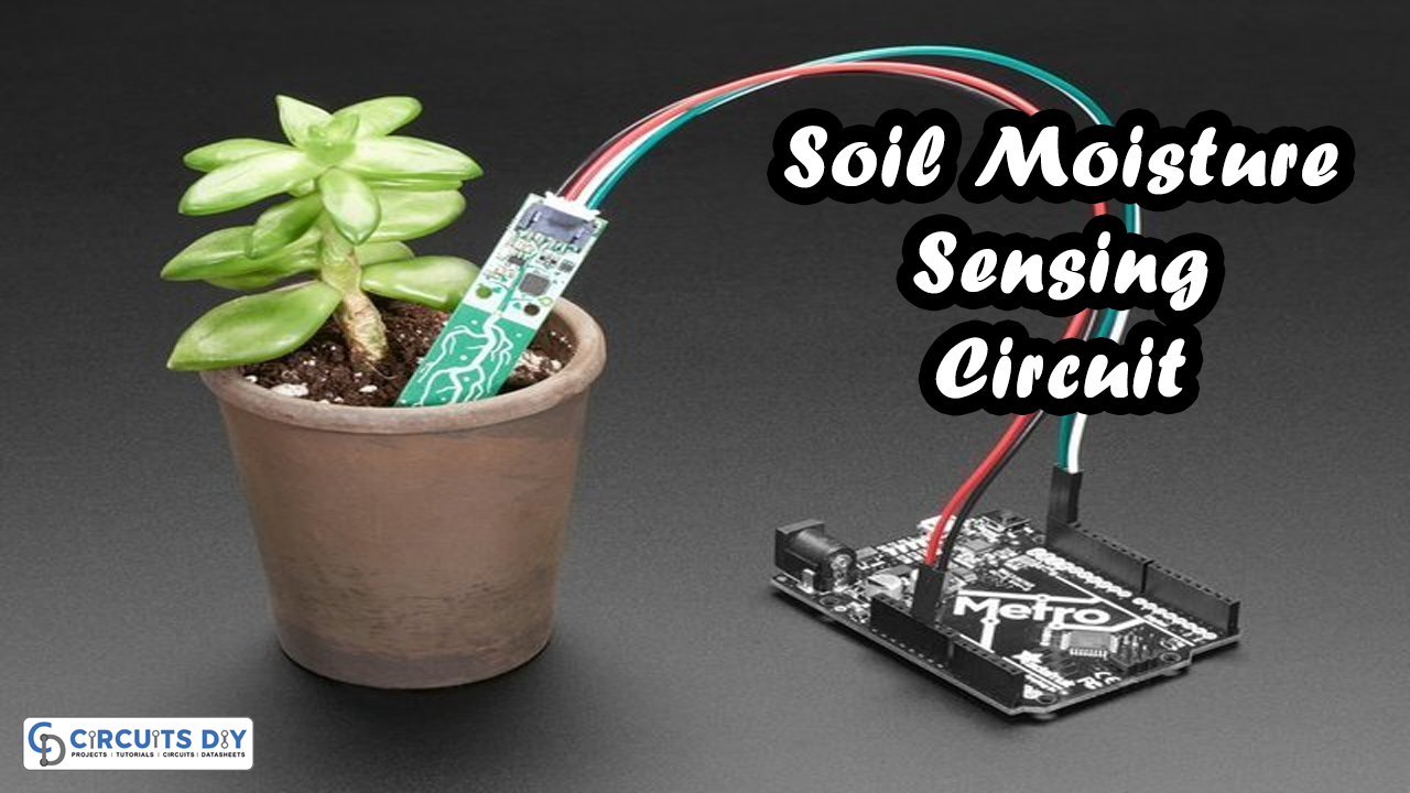
Soil Moisture Sensing Circuit Circuit Diagram The relay contacts switch OFF the motor pump. The
Automatic LED Emergency Light Circuit Circuit Diagram 2) Surge Protected Automatic Emergency Lamp. This emergency
ESP8266 a Complete Beginners Guide IOT 7 Steps Circuit Diagram We have more than 150
Gesture Based Home Automation System Circuit Diagram We created a Wireless Gesture Controller System that
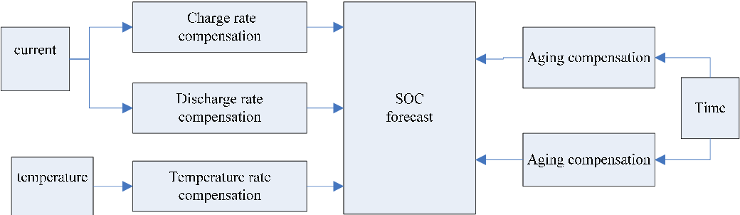
Control System Department Circuit Diagram Future Trends in Battery Management System Circuit Design. In recent
How to use PIR motion sensor without Arduino Circuit Diagram How to Use a PIR