Current Limiter Circuit Diagram for Low Voltage Systems Connect the current limiter in series between the component that you wish to limit its current and the voltage source. If red clip is connected to posive terminal, the black clip must connected to Vcc of the component. Check before apply some voltage. The photo show I dimming a 3W LED with a current limter.

Transistors are used in current limiter circuits, which provide a flexible and manageable method of shielding delicate components from high current. This simple current limiter circuit using transistors secure electronic devices against harm by limiting current to a predetermined amount by leveraging the transistors capacity to control current Generally your current limiting circuit will require a bit of voltage "headroom" to operate in. That means you'll need an unregulated PSU of > 5 V and regulate it down to 5 V while monitoring the current. It's a while since I've read up on the old LM723 voltage regulator but they offer voltage and current limiting. These were very popular once

2 Best Current Limiter Circuits Explained Circuit Diagram
Great site. I need a simple current limiting circuit for a 12v solenoid valve on a sailboat hyrdraulic steering system. Cannot live with the power consumption of 2 amps to hold the solenoid open and it is not necessary. For limiting current you may use the first design given in the article above…..use LM338 for the IC and 0.3 ohms, 1/2
Audio Amplifiers: Audio amplifiers can benefit from the use of current-limiting circuits to safeguard both the amplifier and speaker against excessive current caused by overload or short circuits. This helps prevent component damage and ensures safe and reliable operation. Design Considerations for Current Limiting Circuit
PDF Power Supply Current Limiting Circuit Diagram
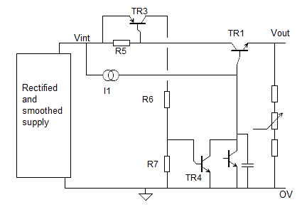
Figure 1 shows a simple current limiting circuit. As the current through the two diodes in series begins to rise, they begin to conduct. This lowers the voltage at the base of the transistor and thus reduces the amount of current passing through the collector - emitter junction and subsequently to the output. So what I need is a simple circuit at the output of the driver which: has low resistance of below 10 Ω if output current is under 100 mA; rapidly increases its resistance to limit the driver current at 500 mA level or lower; withstand capability at short-circuit current shall be at least 20 ms for short circuit to be detected and driver