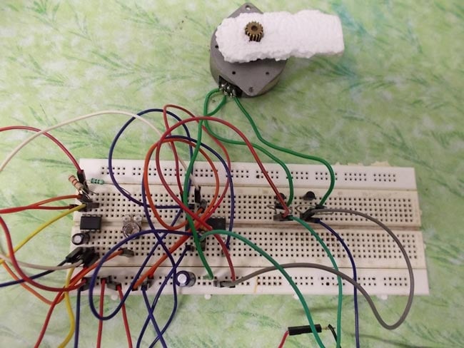
Circuit Diagram For Stepper Motor Driver Here is the circuit diagram of a simple stepper motor controller using only elementary parts. The driver circuit uses, four transistor (SL100) to drive the motor windings, two NOT gates and one XOR gate to decode the two bit control logic to drive the four windings of the motor.
Observe Motor Behavior: The stepper motor should rotate in both clockwise and counterclockwise directions based on the program's delays and logic. Conclusion. In this project, we successfully designed a motor driver circuit using the ULN2003ADR to control a 28BYJ-48 unipolar stepper motor with an Arduino. By leveraging the ULN2003ADR's high

TB6600 Stepper Motor Driver with Arduino Tutorial Circuit Diagram
The circuit diagram has a two-stage stepper motor driver. Here the timer IC 555 works as an astable multivibrator to generate a clock or a square wave. And produced a square pulse based on the timing resistor and timing capacitor.

A Stepper Motor Driver is a circuit or device that provides the necessary current and voltage to a Stepper Motor so that it has a smooth operation. A Stepper Motor is a type of DC Motor that rotates in steps. Circuit Diagram. Components Required. 555 Timer IC; CD4017 Johnson Decade Counter (10 Decoded Outputs) 4 x 2N2222 NPN Transistors;
Stepper Motor Controller Circuit Circuit Diagram
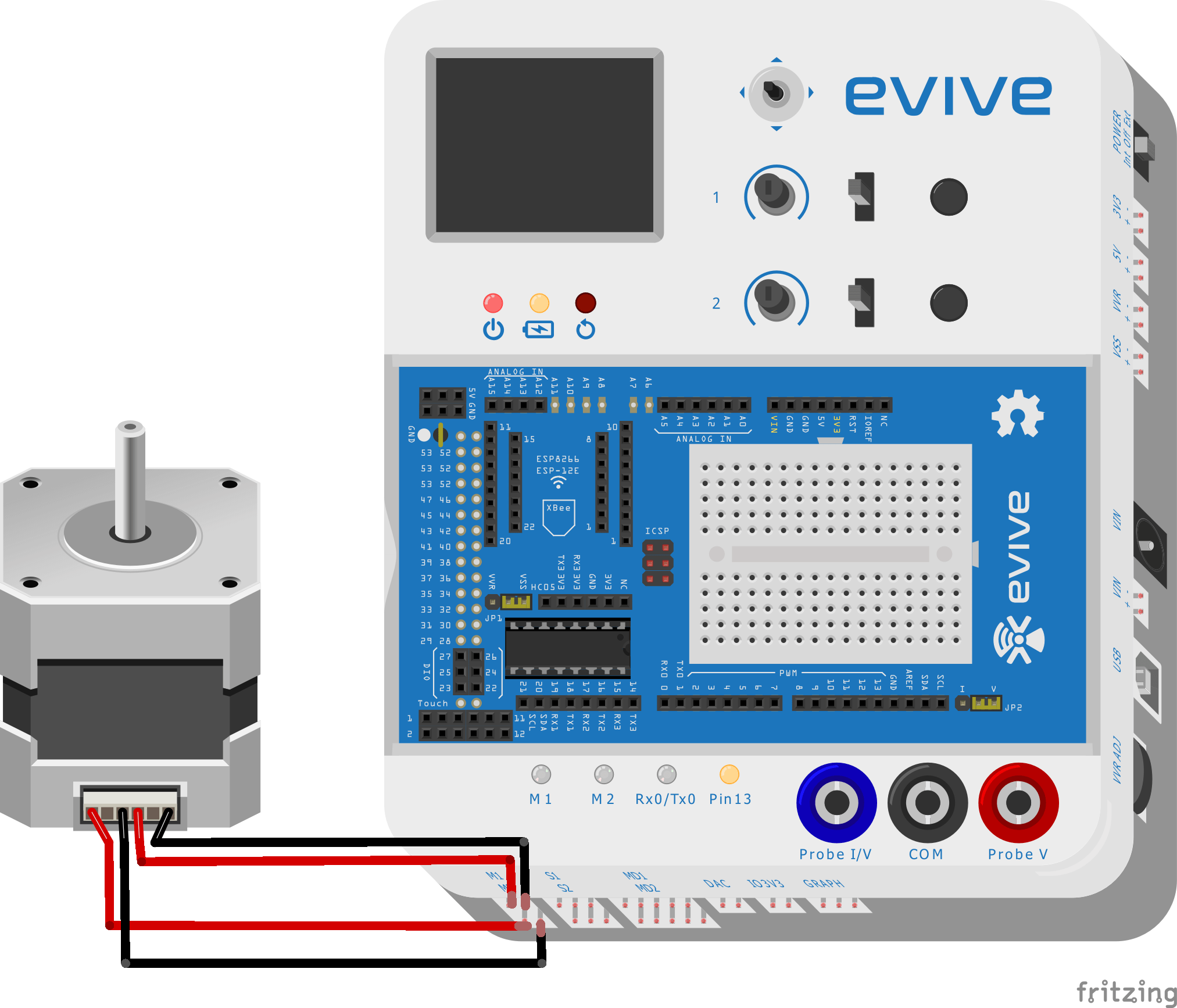
Key learnings: Stepper Motor Driver Definition: A stepper motor driver is defined as a circuit used to drive or run a stepper motor, consisting of a controller, a driver, and motor connections.; Essential Components: Key components include a microcontroller, a driver IC like the ULN2003, and a regulated power supply.; Stepper Motor Controller: The controller must have at least 4 output pins Simple Stepper Motor Driver Circuit Diagram Using 555 Timer Ic. Stepper Motors Code Circuits Construction. Arduino Unipolar Stepper Motor Control Simple Projects. Stepper Motor Generator Eeweb. Hybrid Stepper Motor Working Circuit Diagram Construction Electricalworkbook.
